
What Are the Top Thermal Fluid Heat Exchange Solutions?

Time:2026-10-31 Author:Sienna
0%

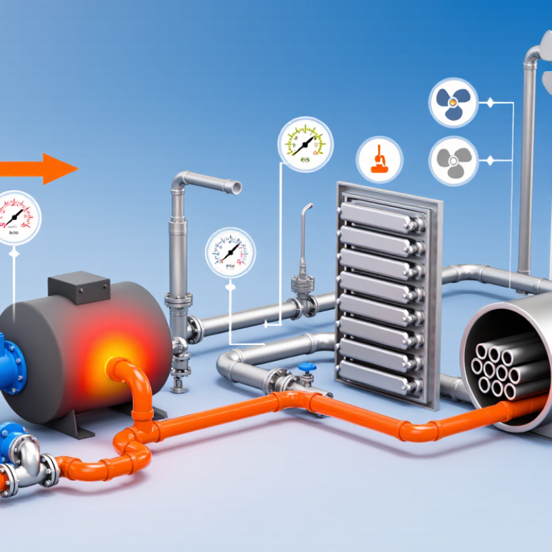
A thermal-fluid system can look simple on a process diagram: a pump moves hot oil through a heater, then a heat exchanger transfers energy to equipment or another fluid. In practice, temperature stability, flow rate, pressure drop, and fluid condition all shape performance. A plate exchanger may suit compact installations, while a shell-and-tube design can be easier to inspect in some demanding services. Air-cooled units may reduce water use, but their output can vary with ambient conditions. The right choice depends on the process, not a product label.

This guide examines thermal fluid heat exchange solutions through practical selection factors, common equipment types, and operating considerations. For example, a plant handling viscous oil may need wider passages and careful attention to fouling. A small leak matters. Operators should also consider cleaning access, gasket compatibility, expansion, and the consequences of an unexpected shutdown. These details are easy to overlook when comparing only purchase prices or headline efficiency figures.

No single design fits every site. A unit that performs well during commissioning may behave differently after months of deposits, changing loads, or neglected maintenance. That deserves a closer look. Reliable selection starts with verified process data and a clear account of operating conditions. The sections ahead explain what to compare, which trade-offs deserve attention, and what questions engineers can ask suppliers before specifying a heat exchanger.
What Are the Top Thermal Fluid Heat Exchange Solutions?

Thermal-Fluid Exchange Basics: Calculate Duty with Q = ṁCpΔT

Thermal-fluid exchanger selection starts with a duty estimate, not a catalog rating.

Use Q = ṁCpΔT:

Q is heat-transfer rate, ṁ is mass flow, Cp is specific heat, and ΔT is the fluid’s temperature change. Keep units consistent; kg/s × kJ/(kg·K) × K gives kW.

For example, 1.2 kg/s of thermal oil with Cp of 2.3 kJ/(kg·K), cooling by 40 K, transfers about 110 kW. Check the units. Actual oil heat capacity varies with temperature and formulation, so use verified fluid data rather than a convenient constant.

This estimate is only a starting point. It assumes steady flow and does not include heat loss, fouling, or exchanger approach temperature.

The International Energy Agency’s Energy Efficiency 2023 report estimates that industry accounts for roughly 37% of global energy use, making avoidable process losses worth measuring.

Shell-and-tube exchangers can suit demanding duties; plate units offer compact heat-transfer surfaces when pressure and fluid cleanliness allow. Double-pipe designs may fit smaller loads.

Compare pressure drop, fouling risk, and operating temperatures before choosing. A calculated duty can look precise while hiding uncertain inputs.

Measure inlet and outlet temperatures under stable operation, then revisit the estimate if actual flow or fluid properties differ.

Compare Shell-and-Tube, Plate, and Coil Exchangers by Duty

Thermal-fluid exchanger selection begins with the required duty: heat load, inlet temperatures, flow rates, and allowable pressure drop.

The U.S. Department of Energy’s 2015 Improving Process Heating System Performance sourcebook estimates process heating consumes about two-thirds of manufacturing energy. That figure covers process heating broadly, not exchanger savings, but it shows why poor sizing matters.

Shell-and-tube units suit large duties, higher pressures, and streams that may foul; removable bundles can simplify maintenance. They need more floor space, though. For viscous oil, check cold-start pressure drop, not just steady-state performance.

Plate exchangers deliver strong heat transfer in a compact footprint, making them attractive when temperatures approach each other closely. Gasket limits, pressure rating, and fouling risk can narrow their useful duty range; welded designs change that trade-off.

Coil exchangers fit localized heating in tanks or vessels, where installation simplicity matters more than maximum area. Their actual capacity depends on coil geometry, circulation, and fluid mixing.

Fit matters. Compare all three at the real operating conditions, using duty calculations and vendor-independent thermal design checks. DOE’s energy estimate is useful context, but it cannot choose the exchanger for a specific plant. A missed detail, like startup viscosity, can undo an otherwise tidy comparison.

Match Heat-Transfer Fluids to Service: Mineral Oils Often Limit Near 300°C

What Are the Top Thermal Fluid Heat Exchange Solutions?

Selecting a heat-transfer fluid starts with the actual service temperature, not the heater’s nameplate rating. Mineral oils often suit moderate-temperature systems, but many formulations approach practical limits near 300°C. That figure moves. The fluid supplier’s maximum bulk and film temperatures matter, as do pressure, oxygen exposure, and heating rates. A fluid can degrade faster when it sits against an overheated surface, even if the system’s average temperature appears acceptable.

For higher-temperature duty, engineered synthetic fluids may offer greater thermal stability, but they are not interchangeable drop-ins. Check viscosity across startup and operating conditions, compatibility with seals, and the fluid’s expansion behavior. Some systems use molten salts for very high temperatures, though their freezing point and material compatibility require careful management. There is no universal best choice. The correct match depends on heat load, circulation design, maintenance capacity, and the consequences of a leak or shutdown.

In practice, an early temperature estimate is often revised after measuring hot spots and return-line conditions. Keep records. During commissioning, sample the fluid and check for oxidation, viscosity changes, or deposits. A small trend can reveal trouble before fouling reduces heat transfer. Engineers should also confirm that pumps, expansion tanks, and safety controls are rated for the chosen fluid and operating envelope.

Design High-Temperature Loops: Some Synthetic Fluids Operate Near 400°C

Synthetic-fluid loops can approach 400°C, but that figure is a design boundary, not a casual operating target. NREL’s 2011 SAM physical-trough technical manual uses about 400°C as the upper limit for conventional synthetic-oil heat-transfer fluid. Near this temperature, small control errors matter. A pump seal, expansion tank, or stagnant pipe section can become the weak point. The margin matters.

Design the loop around measured bulk and film temperatures, not the fluid’s headline limit. Use adequate flow, insulation, and expansion capacity, then check startup and shutdown conditions. NREL’s 2011 SAM power-tower model uses nitrate salt between 290°C and 565°C, illustrating why hotter systems often require a different fluid and equipment strategy. That comparison is not a direct substitute for project testing: chemistry, pressure, and heat-transfer surfaces change the limits. Leave room for fouling and sensor uncertainty; engineers sometimes trust a neat calculation too much. Before commissioning, verify fluid condition and temperature readings at the hottest locations.

What Are the Top Thermal Fluid Heat Exchange Solutions? — Design High-Temperature Loops: Some Synthetic Fluids Operate Near 400°C

Heat-Transfer Medium Typical Upper Operating Range Key Advantages Design Considerations Common Applications
Synthetic aromatic fluid Some formulations are designed for bulk-fluid operation near 400°C Suitable for high-temperature liquid-phase heat transfer; can provide stable heat delivery in closed-loop systems. Check the fluid’s specified maximum bulk and film temperatures, vapor pressure, materials compatibility, and required system pressure. Some formulations have relatively high freezing points and require heat tracing during shutdown. High-temperature process heating, chemical production, and thermal-fluid systems requiring temperatures beyond typical mineral-oil service.
Other synthetic hydrocarbon fluid Formulation-dependent; many systems are designed for service below approximately 350°C, while selected fluids support higher temperatures. Offers a range of operating windows and can be selected to match process temperature and heat-transfer requirements. Do not assume all synthetic hydrocarbons can operate near 400°C. Confirm the manufacturer’s limits for bulk temperature, film temperature, oxidation control, and fluid life. Industrial process heating, reactors, dryers, and circulating heat-transfer loops.
Mineral-oil-based heat-transfer fluid Commonly up to approximately 280–320°C, depending on the fluid and system design. Widely used for moderate-to-high-temperature service and generally familiar to plant operators. High-temperature use can accelerate oxidation, cracking, and deposit formation. Use a properly designed expansion tank, oxygen control, and routine fluid-condition monitoring. Manufacturing processes, heating equipment, and general-purpose industrial thermal-oil loops.
Silicone-based heat-transfer fluid Temperature capability varies by formulation; many commercial systems are used in the approximate 200–300°C range. Can provide useful thermal stability in applications where a silicone fluid’s properties are advantageous. Verify temperature limits, viscosity, seal compatibility, and heat-transfer performance for the specific formulation. It is not automatically a 400°C solution. Specialized process heating, laboratory equipment, and applications requiring silicone-fluid characteristics.
Molten nitrate salt Solar-salt systems commonly operate at temperatures up to about 565°C. Supports very high-temperature heat storage and delivery, including integration with concentrated solar power. Freezing temperatures are high (often around 220°C for common solar-salt mixtures), so pipes and equipment need heat tracing and freeze-protection procedures. Corrosion and salt compatibility require careful design. Concentrated solar power, high-temperature thermal storage, and selected industrial heat applications.
Pressurized water Can be used for high-temperature service, but liquid operation above 100°C requires pressure above atmospheric; near 300°C, saturation pressure is about 8.6 MPa. High heat capacity and strong heat-transfer performance; water is readily available and well understood. Requires pressure-rated equipment, appropriate safeguards, water treatment, and control of boiling and corrosion risks. Design pressure must account for operating conditions and applicable codes. District heating, industrial hot-water systems, and pressurized process loops.

Design note: Temperature limits are indicative, not interchangeable specifications. Select a fluid using its published maximum bulk and film temperatures, operating pressure, freeze point, compatibility data, and the applicable system design code.

Protect Performance by Tracking Flow, Pressure Drop, and Film Temperature

Thermal-fluid systems often reveal trouble through small changes, not sudden failure. A pump may keep running while flow slowly falls below the process target. Track flow continuously, then compare readings with the equipment’s normal operating range. A reduced rate can leave fluid moving too slowly across a heater surface. That can raise local film temperature even when the bulk-fluid reading looks safe. Small differences matter. Use calibrated flow meters and record trends alongside load, startup, and maintenance events.

Pressure drop adds another useful clue. Measure it across strainers, exchangers, and heater circuits under repeatable operating conditions. A rising value may point to fouling, a blocked passage, or increased viscosity. A sudden drop can indicate bypassing, leakage, or a changed valve position. Pair these readings with inlet, outlet, and, where practical, film-temperature data. Operators should verify sensor placement and calibration; a misplaced probe can distort decisions. No dashboard is perfect. Review alarms against field observations, because real systems sometimes behave messily. Document responses, such as adjusting flow, inspecting deposits, or reducing heat input as limits approach.

FAQS

Is 400°C a suitable everyday target for synthetic-fluid systems?

No. It is a design boundary, not a casual operating target. Small control errors matter near that temperature.

Which parts may become weak points at high temperatures?

Pump seals, expansion tanks, and stagnant pipe sections need attention. A quiet pipe can still create a hot spot.

How should engineers check temperature limits?

Measure bulk and film temperatures at the hottest locations. Check startup and shutdown conditions, too. Sensors can mislead.

Why might hotter systems need a different heat-transfer fluid?

Some tower designs use nitrate salt between 290°C and 565°C. That range is not a direct substitute for project testing.

What can a gradual flow decrease indicate?

It may leave fluid moving too slowly across a heater surface. Local film temperature can rise while bulk readings appear safe.

How can pressure-drop readings help operators?

Rising pressure drop may suggest fouling, a blocked passage, or higher viscosity. A sudden drop may point to bypassing, leakage, or a changed valve position.

Which measurements should operators compare?

Track flow, pressure drop, inlet and outlet temperatures, and film temperature where practical. Compare them under repeatable conditions.

What should operators do when readings approach limits?

Verify sensor placement, inspect deposits, adjust flow, or reduce heat input. Dashboards are useful, but field observations can tell a messier story.

Conclusion

Thermal fluid heat exchange solutions transfer energy between process fluids through equipment selected to match the required heat duty, operating conditions, and available space. A useful starting point is the heat-duty equation, Q = ṁCpΔT, which relates heat transfer to mass flow, specific heat, and temperature change. Shell-and-tube exchangers are suited to robust, higher-duty service, while plate exchangers can provide compact heat transfer where conditions allow. Coil exchangers offer another option for heating or cooling within tanks and vessels.

Fluid choice and operating limits are central to reliable system design. Mineral oils are often limited to temperatures near 300°C, whereas some synthetic heat-transfer fluids can serve high-temperature loops near 400°C, subject to their specifications. To maintain performance and protect equipment, operators should monitor flow rate, pressure drop, and film temperature, keeping conditions within the fluid and exchanger design limits.

Sienna

Sienna

Sienna is a skilled marketing professional with a deep expertise in our company’s core products and services. With a passion for innovation and detail, she plays a pivotal role in crafting insightful blog posts that not only highlight the unique features of our offerings but also provide valuable......